CV Carburetor Modifications
For EVO and Twin Cam engines |
Changes to
improve the performance of your Keihin CV carburetor are easy to perform.
| Note: If your engine does not start or idle
properly now, you should attempt determine the cause and repair it prior to making these
carburetor modifications. |
Do not under-estimate the ability of the
stock Keihin CV carburetor to produce good horsepower. The stock CV carburetor has a
venturi diameter of 40mm (1.575 inch). Properly tuned, a CV carburetor is capable of
supporting 80+ horse power in modified engines. A stock bike 1340cc ( 80 CID) can
develop up to 64 horse power with a well tuned and modified CV carburetor. Click
here to see dyno testing on the CV against other carburetors.
With a few parts from your local Harley-Davidson
Dealer and some tools, you can re-jet a CV carburetor and improve the performance of your
bike.
CV
Carburetor Cutaway
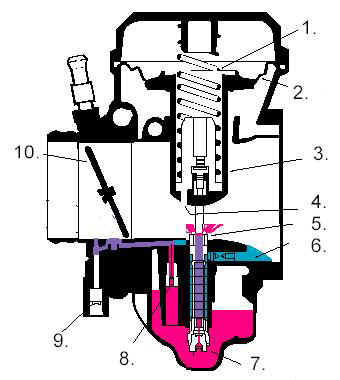
1. Slide Spring
2. Slide Diaphragm
3. Vacuum Slide
4. Vacuum Port
5. Needle Jet
6. Main Air Jet
7. Main Jet
8. Slow Jet
9. Idle Mixture Adjustment Screw
10. Throttle Plate |
Step 1. REMOVE THE CARBURETOR
Remove the carburetor as described the service manual for your model
bike. You might get away with leaving the throttle cables connected. It is much easier to
remove the carburetor and use a work bench. Leave the choke cable hooked to the
carburetor and disconnect the pull-handle end, taking the entire choke cable/carburetor
assembly with the carburetor. It is faster to cut the fuel line hose off rather than
trying to save it.
Tricks of the trade
If you take out the rear fuel tank bolts and loosen the front bolts,
the fuel tank can be raised a few inches. The extra room gained by raising the tank is the
difference between struggling with the job and making it easy.
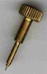
Step 2: MODIFY THE IDLE MIXTURE ADJUSTMENT:
The aluminum plug covering the idle mixture adjusting screw needs to
be removed. Turn the carburetor over and locate the plug toward the rear of the
carburetor, in back of the float bowl. Using about a 1/16" drill bit, carefully drill
a hole through the small plug (CV Carburetor Cutaway item #9).
If the plug does not fall out while drilling, remove the drill bit. Carefully insert
a small self-tapping sheet metal screw into the plug. This will allow enough grip to
remove the plug by pulling on the self-tapping screw with a pair of pliers.
Underneath you will find a slotted screw. Turn this screw clockwise
until it is GENTLY seated. Over tightening this screw can damage the carburetor and needle.
Back the idle mixture screw 2 1/2 full turns. This provides a starting point for tuning. |
Step 3: SLIDE MODIFICATIONS:
Remove the top of the carburetor (slide vacuum chamber cover) being
careful to loosen the throttle linkage stop plate. There is a spring under the top cover,
so hold it with a finger until all screws are loose. Holding the carburetor upright,
remove the cover and spring. The slide/diaphragm assembly can now be removed. Inside the
slide you will see the plastic spring seat. Under the spring seat is the jet needle. These
two items can be removed by turning the slide over and pouring the parts into you hand.
These parts are needed for reassembly of the carburetor.
Slide Detail
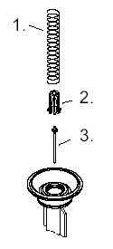 1. Slide Spring
2. Spring Seat
3. Jet Needle |
On the bottom of the slide are two holes. The center hole is for the jet needle. The
second hole is off center. This is the vacuum port (CV Carburetor
Cutaway #4). This hole needs to be drilled to 1/8". Make sure this hole is a
clean straight hole. Keep the shavings away from the rest of the carburetor. Remove
any burrs that exist and clean the slide. Set the slide aside for now.
Step 4: REPLACE JETS:
Turn the carburetor over so the bottom is facing upward. Remove the
float bowl by removing the four screws. Carefully remove the fuel bowl. Using a flat blade
screwdriver, replace the stock #42 slow jet with a #45 jet (CV
Carburetor Cutaway 8). If you use the OEM needle, the main jet will be replaced with a
jet 10 larger than the OEM. If you use the XL needle, the main jet will be
replaced with a 165 jet(CV Carburetor Cutaway 7). The jets are brass parts that are screwed
into an aluminum body. Do not over-tighten the new jets when installing them.
Replace the float bowl, carefully placing the accelerator pump rod
into its rubber boot.
Jetting Notes:
Be sure to use jets numbered for the CV carburetor, and the older
butterfly carburetors. The HD part numbers listed are correct. Additional jet sizes and
jet needles are listed on the CV Carburetor Parts appendix.
|
Step 5: RE-ASSEMBLE THE CARBURETOR:
If you use the OEM needle, place 1 (approx. .050" or
1/16" thick) of the small brass washers over the long end of the needle jet (Slide Detail 3). These washers will
raise the jet needle taper, richening the low RPM fuel mixture. Place the jet needle into
the slide, making sure the washers remain in place. If you did not get thin brass washers,
a single small washer of up to 1/8" thick can be used. Make sure the washer is the
smallest that can be found.
If you are using the XLH needle, place the jet needle into the slide
without using any washers.
Replace the spring seat into the slide and over the jet needle.
Place the carburetor slide into the carburetor body. Carefully place the edges of the
diaphragm into the grove around the top of the carburetor. Install the slide spring and
the carburetor top being careful not to mis-align or pinch the diaphragm.
Assembly Tricks for the diaphragm
The diaphragm is easily mis-aligned or pinched. This is a common
source of problems after carburetor modifications are performed. The diaphragm frequently
has the appearance of being too large to fit into the groove. The repeated up and down
movement of the diaphragm causes it to stretch, making re-assembly tricky. Try using the
cap to position the diaphragm. It will allow you to evenly push the diaphragm into the
groove. You can "wiggle" the top and feel when the diaphragm is properly
located. A damaged diaphragm will have the symptoms of the engine being able to idle, but
will not accept any throttle. If you think the diaphragm is damaged, check for any
pinholes with a bright light behind the rubber, pulling on the edges to stretch the
diaphragm a bit. If you find any, the entire slide/diaphragm assembly must be replaced.
Step 6: PUT THE CARBURETOR BACK ON THE BIKE
The carburetor is now ready to be installed back on the engine.
Place the fuel line on the carburetor before you place it on the bike. Replace the
carburetor, directing the fuel line and choke cable into position as you move the
carburetor into place. Remember to replace the vacuum hose from the VOES to the top rear
of the carburetor. Checking all the work to make sure screws and hoses are properly
installed. Be careful not to over-tighten the choke cable mounting nut as the plastic will
break fairly easily.
Lower the fuel tank back into place. Connect the fuel line hose to
the fuel petcock. If you have a late model bike with the vacuum line connected to the fuel
petcock, make sure the hose is connected. |
Step 7: WARMING UP THE BIKE:
Warm the bike up to full operating temperature. Prior to final
adjustments the engine may not idle properly. The carburetor is not as lean as the factory
settings. DO NOT follow the owner's manual directions for cold starting.
Tricks of the trade
A small, flat blade screwdriver about 3" long should be used to
adjust the idle mixture screw. Fumbling around with the wrong screwdriver usually results
in burned knuckles. Make sure the screwdriver works before the engine is started.
To adjust the idle speed, a long, flat blade or #1 Phillips screw
driver should be used. This allows the screwdriver to get past the various obstructions
that exist between you and the idle mixture screw. |
The new procedure is as follows: If the engine is cold, pull choke
out all the way. If the engine is warm, use half or no choke at all. Start the bike,
adjusting choke to reduce the fast idle to a reasonable speed. About 30 seconds later,
push the choke all the way in and use the throttle to keep the bike idling while warming
up. The throttle lock can be used for this purpose during initial adjustments.
Letting the bike idle for 15 minutes to warm up is not desirable.
The modifications made to your bike should allow it to run well enough for a sedate test
run around the block. This speeds up the warm-up time and also allows a feel for the
improvement to throttle response from the modifications. As the bike comes up to proper
operating temperature, adjustments to the idle mixture and idle speed can be performed. |
Step 8: ADJUSTING IDLE MIXTURE:
With engine warmed up and at idle, turn the idle mixture screw
inward (clockwise) slowly until the engine starts to stumble. If the engine will not idle
on its own during this procedure, raise the idle by adjusting the idle set screw until it
does. Make a mental note of the position of the clock position of the screwdriver. Now
turn the idle mixture screw outwards until the engine begins to run smoothly, adjusting
the idle stop screw as necessary to maintain proper idle speed. Blip the throttle a time
or two and observe the results. If the engine responds quickly with a gratifying blast and
no backfiring through the carburetor, you have your idle mixture right. If backfiring
occurs through the carburetor then adjust the idle mixture screw out another 1/8 to 1/4
turn. Under normal circumstances, the idle mixture screw should be between 2 and 3
turns out. Adjusting the idle mixture screw out to far results in an overly rich, low
RPM fuel mixture leading to poor gas mileage and carbon buildup in the combustion chamber.
Big Twin Idle Speed
The proper idle speed for Big Twin engines is 900-1000 RPMs. EVO
oiling systems need better than 700 RPM to work properly. Resist the temptation to lower
the idle excessively. It may sound good, but improper oiling will contribute to engine
overheating while idling in traffic and premature engine failures. |
Step 9: FINE TUNING:
The details of carburetor tweaking and plug reading is a very
involved subject, so you may want to refer to a higher authority after this. If you do not
have access to a Dyno facility, here is a very basic guide that will get the adjustments
close.
To test the main jetting, you must be in fourth or fifth gear and
running fairly high RPM (4000+) then open the throttle all the way to the throttle stop,
noting the feel of the bike. Immediately let off the throttle about 1/8 turn and note the
feel of the bike. If it seems to accelerate some when you let off the 1/8, your main jet
is too lean. If it hesitates or the top speed is poor (i.e. less than 80 MPH) you are too
rich. Adjust your main jetting accordingly by increasing or decreasing the jet size by 5.
Use your common sense and seat of the pants feel and you will get close enough to do plug
reads.
Plug reading is as much an art as a science, taking years of
experience to understand what the plugs are really telling us about the engine. For
most
street riders, making sure the plugs are a nice light tan color is good enough. Don't read
the plugs until the fine tuning has been done and then make sure you use new plugs. Do
some riding which exercises either low speed or main jetting, then stop immediately
shutting down the engine before it is at idle speed. Checking the plugs this way will
provide the most accurate reading. If your plugs are black you are too rich, which
decreases your gas and performance but will not harm your engine. Too light or worse yet
bone white you are too lean, and engine damage will soon follow if proper steps are not
taken richen the mixture. |
Parts
needed:
CV Modification using the OEM jet needle jet
 | Use OEM Main needle |
| 27114-88 Main jet (#180) or 10 larger than the
stock jet. |
| 27170-89 Pilot or slow jet (#45) or next size
larger (42>45>48) |
| 5 Small, thin brass washers approx. .050 thick (optional for fine
tuning) |
| 2 feet fuel line hose (1/4" ID) |
| 2 small hose clamps for fuel line |
OR
CV Modifications replacing the OEM jet needle
| 27094-88 Main needle ('88 XLH part) |
| 27116-88 Main jet (#165) |
| 27170-89 Pilot or "Low speed" jet (#45)
or next size larger (42>45>48) |
| 5 Small, thin brass washers approx. .050 thick (optional for fine
tuning) |
| 2 feet fuel line hose (1/4" ID) |
| 2 small hose clamps for fuel line |
Having a copy of the Harley-Davidson Service Manual for your model
bike is always extremely helpful. The Service Manual will provide valuable information on
repairs and maintenance of your bike. |
Tools
needed:
Disclaimer:
These modifications are for off-road use only and are not
approved by the Harley-Davidson, EPA or DOT. The authors are not responsible for any
damages due to following these instructions. If you follow them correctly and do not screw
up you should not have any trouble anyhow.. |
| |
|